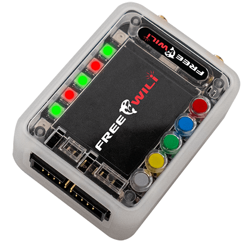
Free Wili - Sub Ghz Tool
Okay New tool time, possibly too new to see if this will actually take wings, but something to play with and learn about. As i love playing with subghz tech and subghz pip boy sounded like fun.
Now to learn it all ^ _^ but the fact it has flashy led's and can be used for car hacking as well as other mischief. Lets see what we can do.
This page will be updated with latest resources and new capabilities added.
Anyways onto the tech porn

Features
SPI, I2C, PIO, and UART available on GPIO
3 USB interfaces (Integrated HUB with 2 FS, 1 HS) for communication and power
11 GPIO Programmable voltage level for 1.1 to 5.5V with 24ma@3V or 32ma @5v (sn74lxc1t45)
2 GPIO for I2C voltage level between 0.9V to 5.5V with software enabled 10K pulls (PCA9517)
GPIO front end includes ICE40UP5k FPGA with 8MByte SRAM and High Speed USB (FT232H)
Two SMA connectors for antenna for longer range
320 x 240 Color Display
5 User configurable buttons
7 Full color LEDs
IR transmitter and receiver
Digital Speaker and Microphone
Raspberry Pi Pico (RP2040) Open Micro Platform for specific applications or custom code
Orca modules plug into GPIO header allows expansion for specific use cases
IO App firmware allows exercising all IO, USB Host API and Standalone scripting
16 Mbyte x 2 on board storage (22 MByte usable)
1000 ma Lithium ION battery with integrated charger
Real Time Clock (RTC)
Accelerometer
Radio Versions
CC1101 Sub Ghz Radios with programmable filter ranges for 300-348, 387-464, 779-928 bands.
Now what can, or will you be able to do with it, in theory quite a few things, still learning about field programmable gate arrays and what one can do with them, So short answer, needing to go with what i'm being told, and a lot of it's features need software written for the rest to come true.
- Use Cases
I2C USB interface
SPI USB interface
UART USB interface
USB attached screen and buttons
Uart based protocol tool support
TPMS fuzzer or simulator
Keyless Entry simulator/monitor
Cybersecurity penetration testing
Development platform that is 80% done
Learning platform for Embedded Systems
Collecting a series of resources for the device as things come in along time. but to start
Official Resources
Official site - https://freewili.com/products/freewili/
Official Github - https://github.com/freewili
Official Docs - https://docs.freewili.com/
Really good explanation of the GPIO pinout - https://store.intrepidcs.com/product/free-wili/fw-blk
Afformentioned GPIO Pinout
IO Voltage Levels
The IO voltage levels are shared by all the GPIO. To set the voltage level you must inject a voltage on PIN4. This voltage can be set to 3.3v or 5.0v with a jumper. This would be a jumper between pins 2 and 4 for 5V. Or between 4 and 6 for 3.3V.
GPIO Pin Descriptions
The table below describes the pins. All GPIO except dedicated I2C pins can be used bidirectionally depending on the application. So the directions are the default.
| Pin | Description | Default Direction | Notes |
|---|---|---|---|
| 1 | SPI Chip Select Out | Output | |
| 2 | 5V Out | Output | 5V to power IO and external circuit |
| 3 | GPIO27 OUT | Output | RPi 2040 GPIO27 |
| 4 | V PINS IN | Input | Input to set the IO voltage 1.1 to 5.5V |
| 5 | UART1 Rx IN | Input | RPi 2040 UART 1 Receive (GPIO9) |
| 6 | 3.3V Out | Output | 3.3 V to Power IO and external circuit |
| 7 | UART1 CTS IN | Input | RPi 2040 UART 1 Clear To Send (GPIO10) |
| 8 | I2C0 SCL | In/Out | RPi 2040 I2C 0 Clock (GPIO17) |
| 9 | UART1 TX OUT | Output | RPi 2040 UART1 Transmit (GPIO8) |
| 10 | I2C0 SDA | In/Out | RPi I2C 0 Data (GPIO16) |
| 11 | UART1 RTS OUT | Output | RPi 2040 UART 1 Request To Send (GPIO11) |
| 12 | SPI1 RX IN | Input | RPi 2040 SPI 1 Receive (GPIO12) |
| 13 | SPI1 TX OUT | Output | RPi 2050 SPI 1 Transmit (GPIO15) |
| 14 | GPIO 26 IN | Input | RPi 2040 GPIO26 |
| 15 | SPI1 SCLK OUT | Output | RPi 2040 SPI 1 Clock (GPIO14) |
| 16 | SWCLK IN | Input | RPi 2040 debugger clock input for external SWD debugger. |
| 17 | GPIO25 OUT | Output | RPi 2040 GPIO25. GPIO25 also connects to board status LED (same as RPi Pico) |
| 18 | SWDIO | In/Out | RPi 2040 debugger IO for external SWD debugger. |
| 19 | GND | ||
| 20 | GND |
I2C Interface
The I2C interface is connected to the RPi I2C0 peripheral. The I2C Interface uses the chip PCA9517 for buffering.
IO Pins Interface
All the GPIO that is not I2C uses the sn74lxc1t45 for buffering.
